Buckling of transverse bulkheads (part 3)
General
This presentation about the modelling of the vertically reinforced transverse bulkheads is a continuation of presentations “Buckling of transverse bulkheads (part 1) -
Buckling of vertically reinforced transverse bulkheads” and “Buckling of transverse bulkheads (part 2) - Buckling of longitudinally reinforced transverse bulkheads”
Since the bulkheads reinforced in transverse system (stiffeners and PSM are arranged vertically) are the most common bulkheads on OSVs this presentation focuses on the modelling of transverse bulkheads vertically reinforced; however, the conclusions of this study could be extended, as a practical conservative approach, to the transverse bulkheads longitudinally reinforced.
Disclaimer:
This text represents only the author personal opinion about the engineering topics presented. This personal opinion is not comprehensive and definitive and it is rather an invitation for discussions, comments and feedback and shall be considered accordingly.
The author can’ take any responsibility for any type of use of this text.

The simplified modelling of vertically reinforced bulkheads
Additional Information
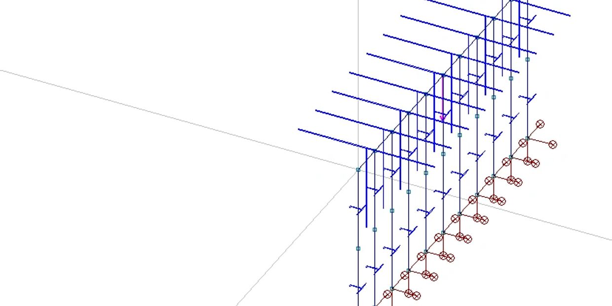
For the purpose of a simple analysis, the vertically reinforced bulkhead is modelled with beams.
Each vertical profile represents the vertical stiffeners of the bulkhead. The top horizontal beam tries to simulate the effect of the deck(s) and bulkhead plates.
A simple bulkhead arrangement was modelled below:
· The bulkhead modelled is extended between two decks spaced 3.0 m. The upper and lower decks are reinforced by deck web frames spaced 2.4 m and are 12 mm respectively 8 mm thick.
· Bulkhead plate has thickness 8 mm;
· The bulkhead is reinforced with HP 200x10 spaced 600 mm.
A force of 500 kN is placed in the middle of the arrangement directly on top of a stiffener (see figure above).
For the first iteration of the study, the upper horizontal element is considered a T section with:
· The flange is the upper deck extended half distance to the nearby web frames; and
· The web is half of the height of bulkhead.
This model is called as Model-1.
Learn More
Visit “Buckling of transverse bulkheads (part 1) - Buckling of vertically reinforced transverse bulkheads”
The forces in stiffeners

Model-1 and further
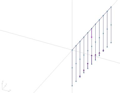
The figure nearby shows the reactions in supports (equal with the axial loads in stiffeners) for Model-1.
Three more iterations have been done. The section of the top element was increased progressive:
· Model-2: The web was extended completely to the lower deck - the profile is still T type;
· Model-3: The contribution of lower deck was added as lower flange - the profile is I type
· Model-4: The section of horizontal profile was modelled as a very stiff section, a huge square 5mx5m. This is just a hypothetical case helpful for demonstrating the point of the study.
The figure above shows the reactions for Model-3. It can be noted that more stiffeners are loaded.

Summary of results
The relation between the rigidities of the top elements in various models can be captured by comparing the radius of gyration ry= Iyy/A.
The table below lists the variation of ratio [reaction]/[total applied force] for each stiffener (s1 to s11) and for each model (Model 1 to Model 4).
Very rigid means even distribution
The graphical representation of the table is presented on the figure below.
It can be observed that the compression loads in smothered by increasing the rigidity of the top horizontal beam. If the rigidity of the top element increases very much, the compressive load is practically even distributed over all stiffeners.
What demonstrates this study?
Discussion
This study demonstrates the extreme sensitivity of the variation of compression forces in the vertical stiffeners to the rigidity of the top horizontal beam.
Unfortunately, it is no standard method or recognized good practice for the quantification of the effect of the top horizontal beam therefore it is not recommended to model the structure of the bulkhead vertically reinforced.
A very rigid boundary condition included in FE models attracts the loads. This is also the case when the bulkheads are modelled as rigid supports.
A better distribution of loads could be achieved by supporting the equipment arranged on vessel’s deck on deck’s girders. Unfortunately, this is not possible in all case therefore the bulkheads are used as support points.
The reality is that the bulkhead structure is elastic but the assessment of this elasticity is difficult and time consuming.
The simple approach discussed above is very attractive for many engineers but the simple test above demonstrates how large variation of the compression loads in the vertical stiffeners could be achieved by the modification of simple parameters of model on the base of apparent straightforward engineering logic.
Learn More
Visit “Buckling of transverse bulkheads (part 2) - Buckling of longitudinally reinforced transverse bulkheads”
Conclusions
What to do now?
Until this issue is clarified the conservative approach shall consider that the bulkhead provides infinite rigid support for the compressive loads.
What should be done?
It is highly recommended that the simple methods for the estimation of bulkhead’s elasticity to be produced and agreed by the industry.
Cookie Policy
This website uses cookies. By continuing to use this site, you accept our use of cookies.