Buckling of transverse bulkheads
General
In general, ship’s transverse bulkheads look very attractive for supporting large equipment installed on board of the ship. Due to this perception, the buckling of transverse bulkheads could become a major risk for a temporary installation of equipment because the consequence of buckling could be:
· In the first instance the loss of strength capacity of local elements of the bulkhead followed by the modification of the load path in the structure. The modification of load path in structure is sometime called stress redistribution;
· The loss of strength capacity of the localised structural elements may lead to permanent structural deformations and/or cracks.
In general the consequences of these failures are limited to local aspects but, by the unfortunate sum of events could lead to more severe consequences.
If buckling capacity of bulkheads structure is find not sufficient, the reinforcement of bulkhead for resisting buckling may involve costly underdeck works requesting access in tanks (sometime fuel tanks) or working at height.
Considering the above it is important that the buckling capacity of transverse bulkheads is estimated as good as possible.
This presentation will focus on the assessment of buckling of transverse bulkheads reinforced by vertical stiffeners (transverse system) but more presentations are planned regarding:
· The transverse bulkheads reinforced by horizontal stiffeners (longitudinal system); and
· Modelling the transverse bulkheads.
Disclaimer:
This text represents only the author personal opinion about the engineering topics presented. This personal opinion is not comprehensive and definitive and it is rather an invitation for discussions, comments and feedback and shall be considered accordingly.
The author can’ take any responsibility for any type of use of this text.
Buckling of vertically reinforced transverse bulkheads

The bulkhead is partially extended under upper deck and it is supported only at ends
In this case, the load is transferred as a shear force to the supports.
The likely buckling of bulkheads elements are due to the shear stress.
The shear stress is estimated and a buckling calculation for the bulkheads panels in the most stressed end is done.
Normally the bending stress is minor for such an arrangement therefore the effect of normal bending stresses resulted from the application of load is in general not significant.

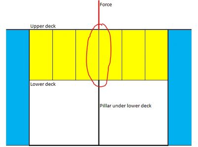
The bulkhead is partially extended under upper deck and it is supported only at ends and under the load by a beam type pillar
In this situation, the load is transferred directly into the pillar below via the stiffeners aligned with pillar.
The stiffener has to be capable transferring the load with no more contribution of other structural elements of bulkhead.
The buckling capacity of the stiffener integrated in bulkhead shall account only a plate strip 40*t where t is the thickness of bulkhead plate in area. Normally the minimum thickness shall be considered but some advantage could be taken if larger thickness is arranged mid length but also extended until a reasonable high position below the upper end.
Note: 40*t is considered the width of plate capable to stay loaded with compressive stresses together with the stiffener in case the plate field in between stiffeners buckle.

The bulkhead is continuous to the bottom of ship
In this situation the redistribution of stresses in the bulkhead structure may be possible if bulkhead plate is capable to carry the load without buckling.
This case is the most complex and may involve few calculations loops presented in the following section.
Typical stiffeners - Calculations loops

1st step:
The buckling capacity of stiffener below the load Fcr-0 is estimated for plate strip 40*t. If F ≤ Fcr-0 the strength is considered sufficient. If this is not true the 2nd step is done.
2nd step:
The area A1= 2*s*t+Astiffener-0 is used for estimating the value of stress just before the stress spread intersect the adjacent stiffeners.
s= stiffeners space;
Astiffener-0 = area of stiffener below the load with no additional plate;
sigma1= F/A1 ;
The stress sigma1 is used for estimating the capacity of plate between adjacent stiffeners to transfer load. This capacity is estimated by a plate buckling calculation for a panel with width s and length 2s loaded along the long axis with s1.
The plate can transfer the load to the adjacent stiffeners if the results of plate buckling calculation of the panel above is positive. If this is not true the 3rd step is done.
3rd step:
The area A2= 3*s*t+Astiffener-0 + Astiffener-L + Astiffener-R is used for estimating the value of stress just before the stress spread intersect the adjacent stiffeners.
Astiffener-0,L,R = area of stiffeners with no additional plate;
sigma2= F/A2
The critical stresses in stiffeners, sigma2, are calculated but this time a plate strip with width s is considered instead of 40*t.
If the critical buckling stress for each stiffener is larger than sigma2 the buckling check is considered satisfactory.
Shortcut for 3rd step:
A shortcut for 3rd step is just checking the buckling capacities of stiffeners for 50% of load for the stiffeners located directly under the load and 25% of load for each adjacent stiffener considering full space between stiffeners for the estimation of buckling capacity.
The load could be applied also in between stiffeners
In this case, the first step is the verification of the buckling capacity of plate panel below for transferring the load to the adjacent stiffeners. Normally this calculation is done considering a panel s x s and stress F/(s*t).
The local squeezing effect of bulkhead plate under a direct applied load might be of interest as well.
The actual main rules for ships are not capturing explicitly this effect (possible this effect may be captured for special loads as wheel loads) however it is recommended in special if significant loads are applied on small lengths.
Cookie Policy
This website uses cookies. By continuing to use this site, you accept our use of cookies.